Multi Jet Fusion enables the efficient production of nylon end-use parts using additive technologies. Here’s a checklist for design teams.
What is Multi Jet Fusion?
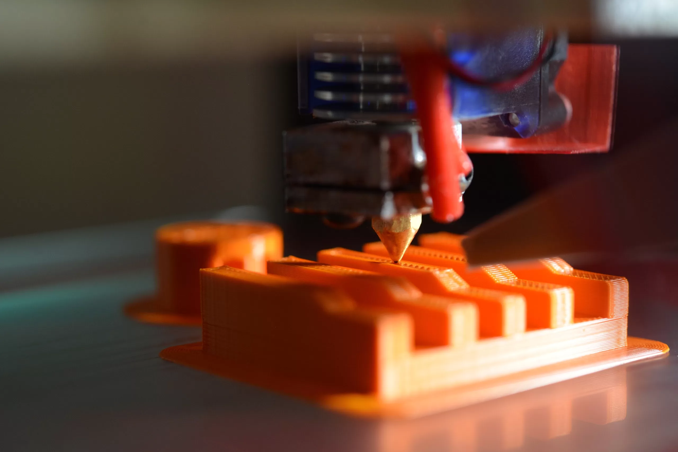
Multi Jet Fusion (MJF) is an industrial 3D printing process that produces functional nylon prototypes and high-volume production parts with exceptional design freedom and mechanical properties. The process uses inkjet nozzles to selectively distribute fusing and detailing agents across a bed layered with nylon powder. The MJF printer uses a continuous sweeping motion to distribute agents and apply heat across the print bed layer by layer until the part is finished. This results in high-quality parts being produced at high speeds.
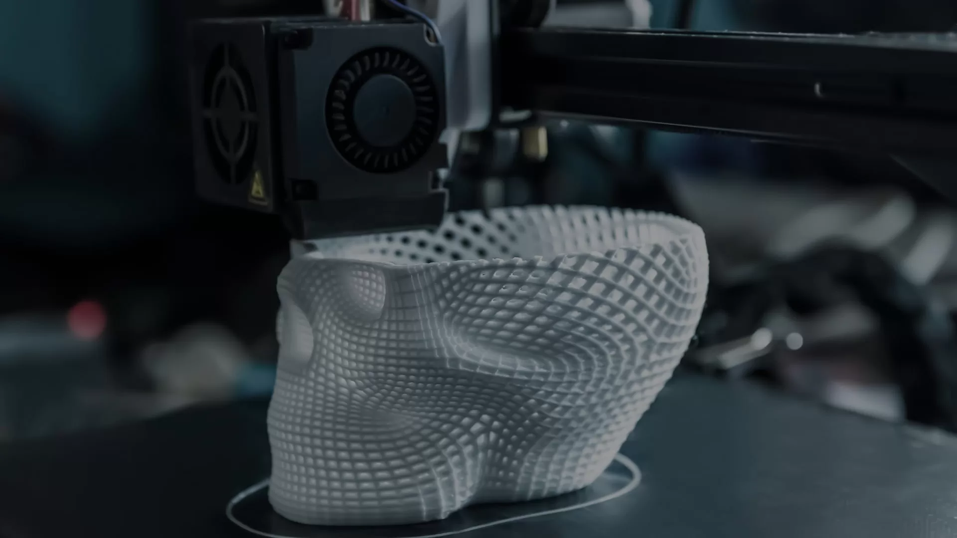
Unlike selective laser sintering, support structures are not required to produce parts, making it possible to create complex geometries like internal channels or co-printed assemblies. MJF parts have mechanical properties similar to those of injection-molded parts, but without the need for expensive tooling.
To ensure optimal part quality and yield, minimize post-processing needs, and drive cost reductions, it is important to design for manufacturability. Follow this checklist to ensure that your team is following MJF design best practices.
1、Is MJF a suitable process for my project?
Before delving into design changes, it is crucial to determine if the MJF (Multi Jet Fusion) process aligns with all the requirements of your project. To assist you in making an informed decision, consider the following questions:
Do any of the available materials meet my product requirements?
MJF possesses numerous strengths; however, it is worth noting that it has a limited selection of approved materials. PA12 and its glass bead counterpart are highly versatile for applications involving rigid plastics. TPU, a flexible polyamide, is suitable for scenarios requiring elastomeric materials. If the available materials do not fulfill your specific requirements, it may be necessary to explore alternative manufacturing processes.
Does my part fit within the build volume?
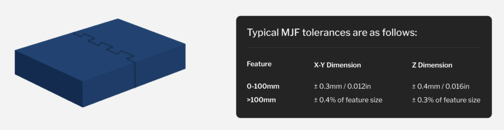
An essential limiting factor to consider is the build volume of the machine, which measures 380 x 380 x 284mm for the Jet Fusion 4200. In certain cases, large parts can be printed as smaller subcomponents and subsequently assembled using adhesive or mechanical joints. Incorporating design features such as dovetail joints can facilitate alignment and enhance adhesion during the assembly process.
Are there any tight tolerances that I need to achieve?
While the gap between additive manufacturing and injection molding tolerances is gradually decreasing, it is imperative to ensure that MJF’s tolerances are suitable within the context of your assembly.
2、Are there areas where I can reduce material usage?
In many cases, defects in MJF can be attributed to thermal gradients that occur during the printing process. Uneven cooling can result in warping or sinkage of the printed piece. Certain part characteristics, such as being long and thin, having abrupt changes in cross-sections, or featuring thin curved surfaces, are particularly susceptible to shrink-induced warping.
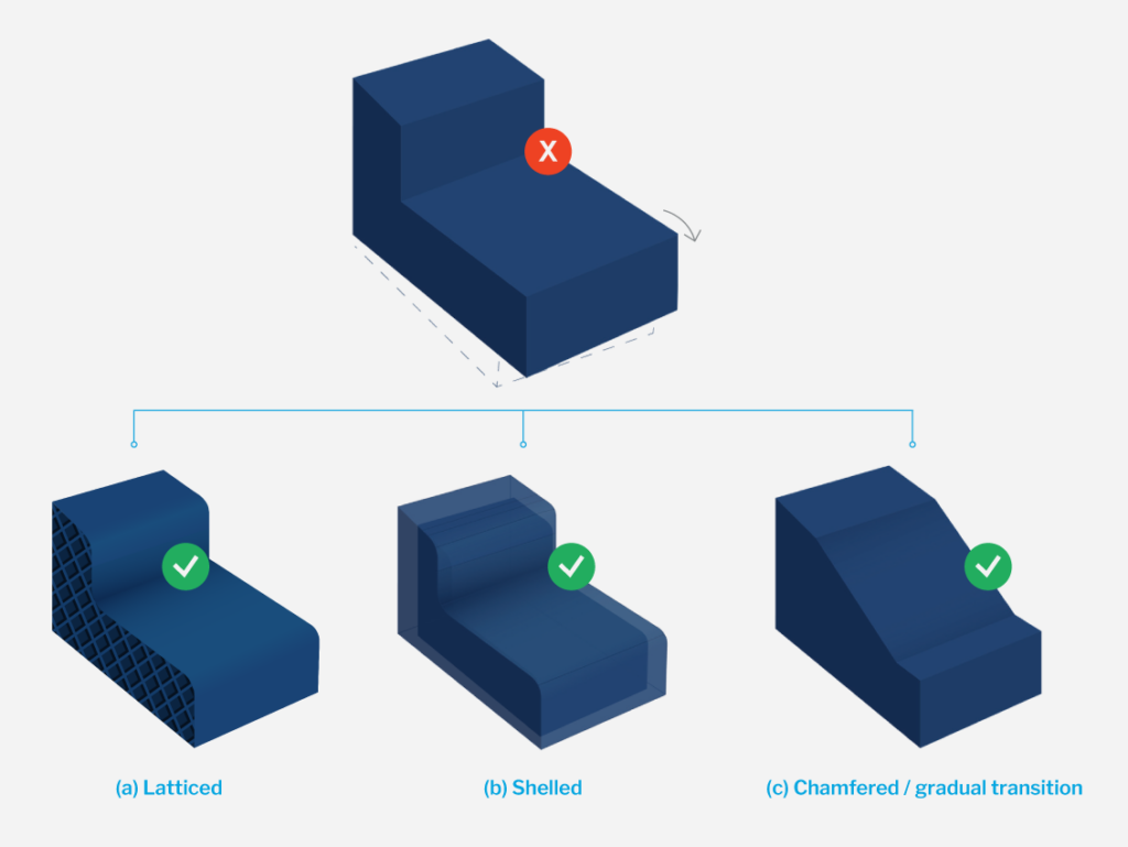
To address this issue, implementing Design for Manufacturability (DFM) changes can be beneficial. Here are some recommended modifications for a part that is prone to warping due to an abrupt change in cross-section:
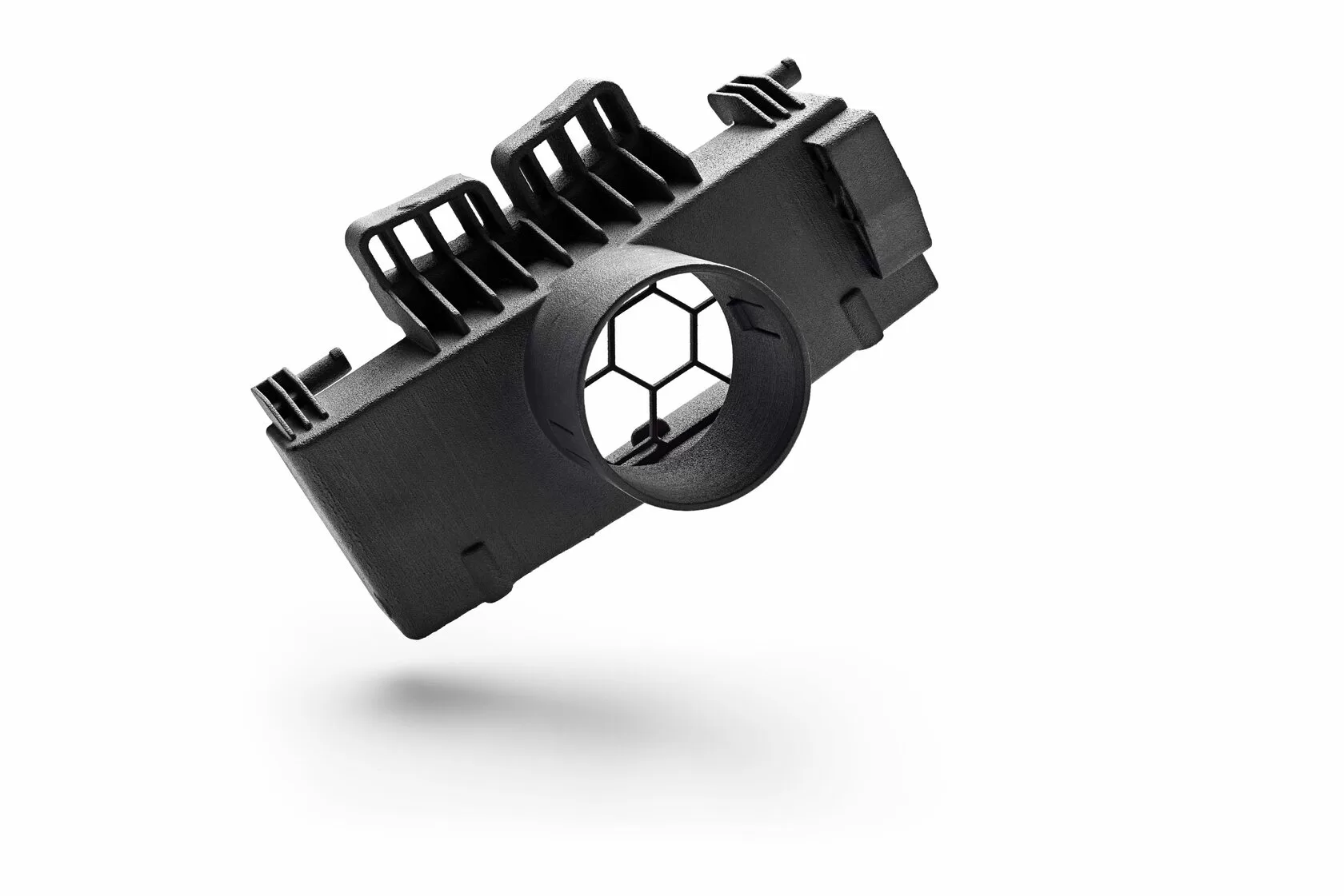
- (a) Incorporate latticed structures: Introduce lattice patterns within the part design to reduce material usage without compromising structural integrity. These lattice structures help distribute thermal stresses more evenly.
- (b) Utilize shell structures: Implementing shell features, where appropriate, involves removing unnecessary material from the internal regions of the part. This not only reduces material consumption but also minimizes the risk of warping.
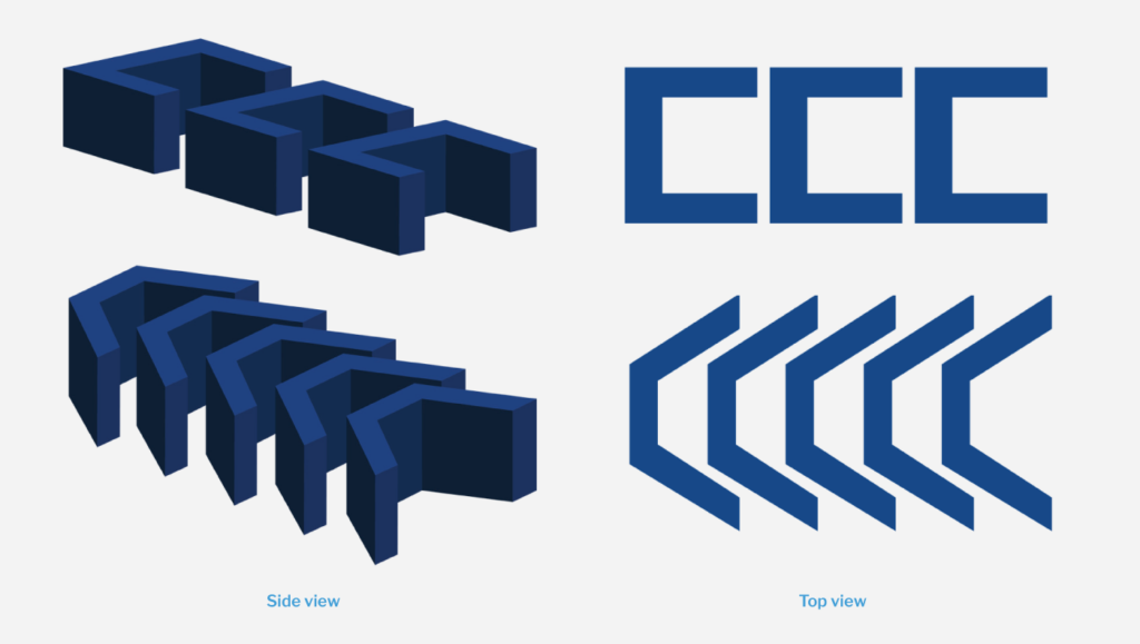
- (c) Implement gradual transitions: Instead of sudden changes in cross-sections, incorporate chamfers or gradual transitions in the design. This ensures a smoother flow between different features, reducing the likelihood of warping.
In addition, consider employing topology optimization techniques to optimize the design for material efficiency and structural integrity.
By adopting these strategies, you can effectively mitigate and prevent defects while optimizing material usage in MJF.
3、Are my features meeting the minimum size requirements?
In general, when designing parts for MJF printing, it is important to consider the minimum threshold size for various features. Here are some guidelines to ensure your features meet the requirements:
- Wall Thickness: The recommended minimum wall thickness for MJF-printed parts is 1.5mm. This ensures structural integrity and dimensional stability.
- Small Design Features: Features such as slits, embossing, engraving, or the diameters of holes and shafts should generally be no smaller than 1.5mm. However, specific exceptions can be made for these features, allowing them to be as small as 0.5mm.
- Embossed or Debossed Text: If your design includes embossed or debossed text, ensure that the font size is no smaller than 6pt (approximately 2mm) and that the depth is a minimum of 0.3mm. This ensures legibility and durability of the text.
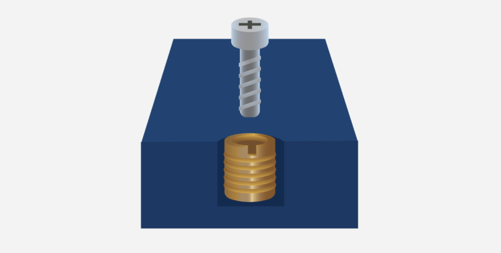
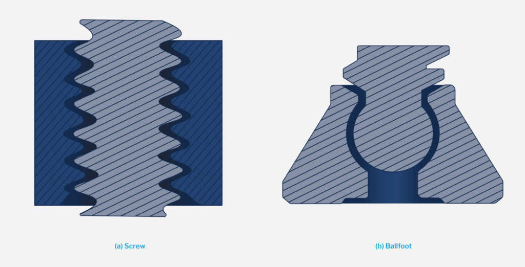
- Screw Threads: If your part requires screw threads, it is recommended to use M6 or larger threads. For smaller, more precise, or more durable threads, consider incorporating threaded inserts into your design.
Additionally, it is important to consider the potential breakage of small, slender features during post-processing. Delicate features may be prone to breakage, so it is advisable to evaluate their robustness and make necessary design adjustments to avoid any issues.
By adhering to these size guidelines and considering the durability and post-processing aspects, you can ensure that your features are suitable for MJF printing.
4、Have I considered assembly tolerances?
Even with the increased geometric flexibility offered by the MJF process, certain applications may still necessitate the assembly of multiple components. It is important to take assembly tolerances into account to ensure proper fit and functionality. Here are some considerations:
clearance to prevent fusing due to higher contact surface-area
- Mating Faces Clearance: It is generally recommended to provide 0.4 – 0.6mm of clearance between mating faces of assembled components. This clearance allows for proper fitting and accommodates any slight variations in dimensions during the printing process.
- Co-Printing Assemblies: In cases where components are printed together as an assembly, it is crucial to provide sufficient clearance. A minimum of 0.5mm of clearance is recommended between the co-printed components. However, depending on factors such as thick cross sections or significant contact surface area, you may need to provide additional clearance to prevent fusing or interference between the printed parts.
By considering these assembly tolerances, you can ensure that the printed components fit together seamlessly and function as intended.
5、Is my part design optimized for post-processing?
If your part requires post-processing, it is essential to consider certain design considerations to enhance the effectiveness of secondary operations. Here are some key points to double-check:
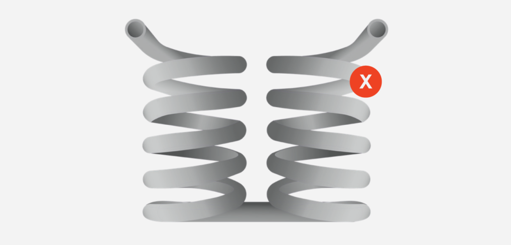
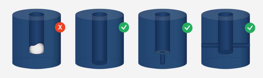
- Unvented or Trapped Volumes: Ensure that your design does not contain any unvented or trapped volumes. These can lead to difficulties during post-processing, such as powder residue or inadequate cleaning. Proper venting and accessibility should be incorporated into the design to facilitate post-processing operations.
- Avoid Blind Holes: Whenever possible, it is advisable to avoid incorporating blind holes in your design. Blind holes are challenging to clean thoroughly, which can increase post-processing costs and potentially compromise the quality of the final product. Consider alternative design approaches that eliminate or minimize the need for blind holes.
- Fillets at Corners: Incorporate fillets at corners where powder can accumulate and become challenging to remove during standard tumbling and bead blasting processes. Fillets help prevent powder caking and improve the efficiency of post-processing operations, ensuring a smoother and more consistent finish.
By addressing these aspects in your part design, you can optimize the post-processing workflow, improve cleaning efficiency, and ultimately enhance the overall quality of the finished product.

6、Have I explored opportunities to lower part costs?
When designing parts for MJF, there are various opportunities to optimize designs and lower part costs. Consider the following aspects to identify potential cost-saving measures:
- Lightweighting: Reducing the weight of your part not only helps minimize material costs but also decreases the risk of defects during the printing process. Analyze your design to identify areas where material can be removed or optimized without compromising the part’s functionality or structural integrity.
- Nestability: Optimizing the nestability of parts within a build can increase the number of parts that can be printed simultaneously, spreading fixed costs over a larger quantity. Consider adding draft angles or adjusting the position of printed assemblies to maximize the number of parts that can fit in each build.
- Cosmetics and Surface Finish: Evaluate the cosmetic requirements and surface finish needed for your part. MJF parts have a natural grey color, but they can easily be dyed black if color is not critical. If painting or other surface treatments are not necessary for the part’s function, consider forgoing these processes to reduce expenses. Additionally, the surface finish of MJF parts typically ranges from 125 to 250 microinches RA. If a smoother surface is required, various post-processing techniques such as sanding, tumbling, or vapor smoothing can be considered.
- Texturing: Texturing can be an effective design technique to improve part aesthetics without the need for additional post-processing. Explore options for incorporating textures directly into the design to enhance the part’s appearance and avoid additional costs.
In this example, adding draft enables packing of two additional parts.
By considering these cost-saving opportunities and optimizing your part design accordingly, you can reduce expenses while maintaining the desired functionality and quality of the printed parts.
Getting Started with a DFM Expert
Design for Manufacturability (DFM) is crucial for optimizing manufacturing processes and achieving cost-effective production with high-quality parts. By following DFM principles, you can minimize expenses, identify design issues early, and improve overall part quality. To ensure your MJF parts are optimized and refined before production, consider the following checklist:
- Evaluate Part Design: Review your part design for manufacturability, considering factors such as wall thickness, feature sizes, assembly tolerances, and post-processing requirements.
- Material Optimization: Identify opportunities to reduce material usage without compromising structural integrity. Utilize lattice structures, shell features, and gradual transitions to minimize material consumption.
- Check Minimum Size Requirements: Verify that your features meet the minimum size guidelines for MJF printing, including wall thickness, small design features, embossed/debossed text, and screw threads.
- Consider Assembly Tolerances: Ensure mating faces have appropriate clearance, avoid blind holes, and provide sufficient clearance for co-printed assemblies to prevent fusing or interference.
- Optimize for Post-Processing: Design parts to facilitate post-processing operations. Avoid unvented or trapped volumes, minimize blind holes, and add fillets to corners where powder can accumulate.
- Seize Cost Reduction Opportunities: Implement lightweighting techniques, optimize nestability, consider part cosmetics and surface finish requirements, and explore texturing options to lower part costs.
Partnering with a DFM expert like V1 provides access to digital design technologies and expert guidance throughout the project lifecycle. Our team can assist with design, prototyping and fulfilment, ensuring high quality parts are delivered on time and at a competitive price.
To get started with V1 or to find out more about our services, contact us today. We can help you optimise your MJF parts and achieve your manufacturing goals.